PSRG Voting System
Author: Doug Kingston, KD7DK; Randy Neals, W3RWN
Last Update: 20 December 2021
Background
Until 2018, PSRG had run a single site repeater system, meaning that both the receiver and transmitter are located at the same location, in our case at the John Hayes Elementary School on top of Queen Anne Hill in Seattle.
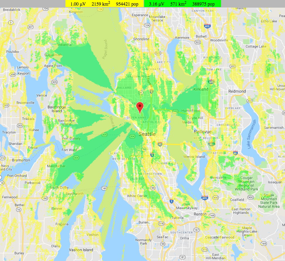
We started running a voting system as described in this document in late 2018, and on July 4th, 2019, we moved the primary repeater and therefore the transmitter to the Seattle Housing Authority Capitol Park Apartments on Capitol Hill, and removed our presence from the John Hayes school. Queen Anne did amazingly well for a modestly located repeater, but Capitol Park has a height and height above average terrain advantage. The superior power system and access was another important factor. In addition, the group maintains a backup, single site repeater on Beacon Hill on top of the Seattle Housing Authority building there. Beacon provides a good backup site, but the system does have holes in its coverage. In particular, coverage of the south end of Seattle is spotty from Capitol Park and it’s quite marginal around Seatac. There is also shading caused by our hilly terrain and areas like Madrona have problems because of this, and there are weak areas on the east side of Lake Washington. The increasing use of low power handie-talkies causes an imbalance talk-in/talk-out of the repeater.
Voting System Overview
We have undertaken to improve the PSRG system by adding additional receivers, and a receiver voting system that will choose the receiver with the best incoming signal to forward on to the repeater transmitter. The current local receiver will be just one of the receivers. We are currently running 6 receivers but we are not limited to that number. The primary transmitter is currently at Capitol Park and the backup transmitter will be at the Beacon Hill site. The Capitol Park and Beacon Hill receivers are both active, and voted. In addition to these existing receivers, we have added an additional receivers and in North Seattle (Lake Forest Park, currently offline), Cougar Mountain, Buck Mountain, and Magnolia (at Magnolia Manor Park). Multiple receivers improve the ability for handheld and low power radios to reliably access the PSRG repeater, and will reduce noise on most signals from Seattle and area. After a few weeks of operation on the new system, the benefits were already very evident. We observed several new-to-PSRG hams checking-in to the nine o’clock nets as a result of improved coverage. We continue to review the receivers and their performance and will consider installing new or relocating existing receivers as needs demand.
Receiver Voting Terminology:
Local receiver – the receiver colocated with transmitter (and often the voting system itself)
Satellite receiver – a receiver located remoted from the transmitter and voting system
Voting controller – a small computer at the transmitter location which processes the signals from satellite receivers.
Traditional Receiver Voting
Analog receiver voting is not a new technology, but what is new is the use of Voice-Over-IP technology and an IP communications network (HamWAN) as the transmission medium between the remote receivers and the central site. This digital backbone simplifies the implementation of a receiver voting system, reducing the technical difficulty of audio level adjustment, and audio reproduction.
In a traditional repeater voting system, the satellite receivers are linked back to the main site either via telephone lines or dedicated RF links. At the remote site, the satellite receiver would be connected to a link transmitter. And at the primary site, a link receiver would be configured to listen for the link transmitter. This would be repeated for each additional satellite receiver, resulting in an impressive array of receivers at the main site.
At the main site all link receivers are each connected to the voter. The voter simultaneously computes the signal-to-noise ratio of each link receiver input after it traverses its entire path (satellite receiver -> link transmitter -> link receiver -> voter) and then chooses the voter input with the best S/N ratio to pass on to the transmitter. All the voting logic is in one location, the main site. A significant effort is expended in aligning all the receivers, link transmitters and link receivers to have identical audio levels and audio processing.
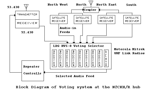
More detailed explanation on traditional voting systems can be found here:
http://www.repeater-builder.com/tech-info/voting-comparators.html
We are not using a traditional analog voting system.
The Allstar Voter System
The Allstar Voter System utilizes Voice-Over-IP technology, and in the Seattle area we are fortunate to have the HamWAN IP network which will serve as our linkage between remote receivers and the Queen Anne central site. In some cases we are also using the public Internet to support our satellite receivers, but prefer to use HamWAN which is independent of the Internet.
The Allstar system uses a small interface box called a Radio Thin Client Module (RTCM) which is attached to each receiver and transmitter in the system. They are manufactured by Micro-Node International. The RTCMs are connected back to the voting controller over an internet connection.
The connections to the RTCM include:
- Receiver discriminator audio
- CTCSS decode signal
- Transmit audio and PTT (if attached to a transmitter)
- GPS receiver including a 1 pulse per second input for microsecond accuracy
- Ethernet connection to an IP network
We have standardized on the Garmin 18x LVC GPS receiver. This unit has the additional 1 PPS signal and is reasonably inexpensive.
The analog received audio from each active receiver is digitized, and batched in 20ms frames (packets) for transmission. The RTCM uses the attached GPS receiver to get a very accurate timing signal and then applies a timestamp to each frame. The RTCM is also digitally measures the signal-to-noise ratio of its received signal and assigns a numeric signal strength metric to each frame (a number from 0-255). Each RTCM is sending a stream of timestamped audio packets with signal strength metric to the voting controller whenever there is an active input signal.
The voter controller is a raspberry Pi running Allstar linking repeater controller software, along with the voter software module enabled. The job of the voter module is to receive the multiple streams of time stamped audio from each receiver, and then choose the frames with the best quality rating to pass on to the Allstar controller and then the transmitter. Because an IP network is asynchronous, some packets may arrive at slightly different times which could introduce jitter in the audio. To avoid this the voter buffers and arranges the frames in time sequence order. A small delay (100ms or thereabouts) is added to the received signal before it’s sent to the transmitter to give the voter time to process the packets and deal with any internet introduced delays. Every few frames, the voter reconsiders which stream is providing the best signal and may dynamically switch from one receiver to another as the receive signal quality changes. The high accuracy of the timestamps and the alignment of audio samples from different receivers prevents noticable changes in the audio as the voter switches between receivers.
A more comprehensive description is available in the original Allstar Voter System Documentation: https://allstarlink.org/votersystem.pdf
More information on the Allstar implementation we are using: http://hamvoip.org
Redundancy and Failover
The Allstar voting system has good support for redundancy and failover.
The RTCM modules can be configured with a primary and backup voting controller address. In our case we are placing the primary voter system controller at Capitol Park with the primary transmitter and the backup voting controller will be at Beacon Hill with the backup transmitter. Each RTCM is constantly exchanging heartbeat packets with the primary (Queen Anne) voter. If it loses connection to the primary voting controller, the RTCM will connect to the backup voting controller, but continue to probe the master in case it comes back online.
The RTCM has a further fail-safe mode which is used if neither voting system controller is available. The RTCM fail-safes as a simple repeater controller, ensuring the repeater with local receiver remains operational. In this mode it has a morse code ID and no courtesy tone, but it will work as a single site repeater until internet connectivity to one of the two voters is restored. We will configure the Queen Anne RTCM to operate in offline mode if it cannot contact either voter.
Finally, because the system is configured in software, it’s easy to reconfigure the active transmitter or alter other system configuration remotely.
User Visible Changes
There are a number of user visible changes from this transition.
- Substantially all repeater users have a full quieting signal into the repeater. This is due to having receivers which provide a more complete coverage of our effective service area.
- The audio quality of Echolink and Allstar linking has improved greatly, a result of processing the audio digitally and removing the analog repeater controller.
- There is a small additional delay through the system to allow the voter to assemble the incoming audio frames from each site and accommodate any internet (HamWAN) delays it encounters with introducing jitter or dropouts. This is currently about 200ms which is noticeable as a small snippet of your audio when you un-key your PTT if you have a fast transmit/receive relay. This is only noticeable by the transmitting stations, others cannot hear this.
- The playback (or DVR) function has changed its command sequence from 12 to *55
- The voice ID (when present) and other voice prompts are different
- The courtesy tone will change depending on the situation:
- The “Normal” RF courtesy tone is a 100ms 800Hz beep.
- The “Link” courtesy tone (when there is an internet station connected to the repeater via Allstar, Echolink or IRLP) is a 100ms 1200Hz beep.
Additional Documentation References
RTCM Manual: http://173.248.148.139/unode_docs/rtcm_%20manual.pdf
Buffer tuning: http://docs.allstarlink.org/drupal/node/108
Sites
Capitol Park
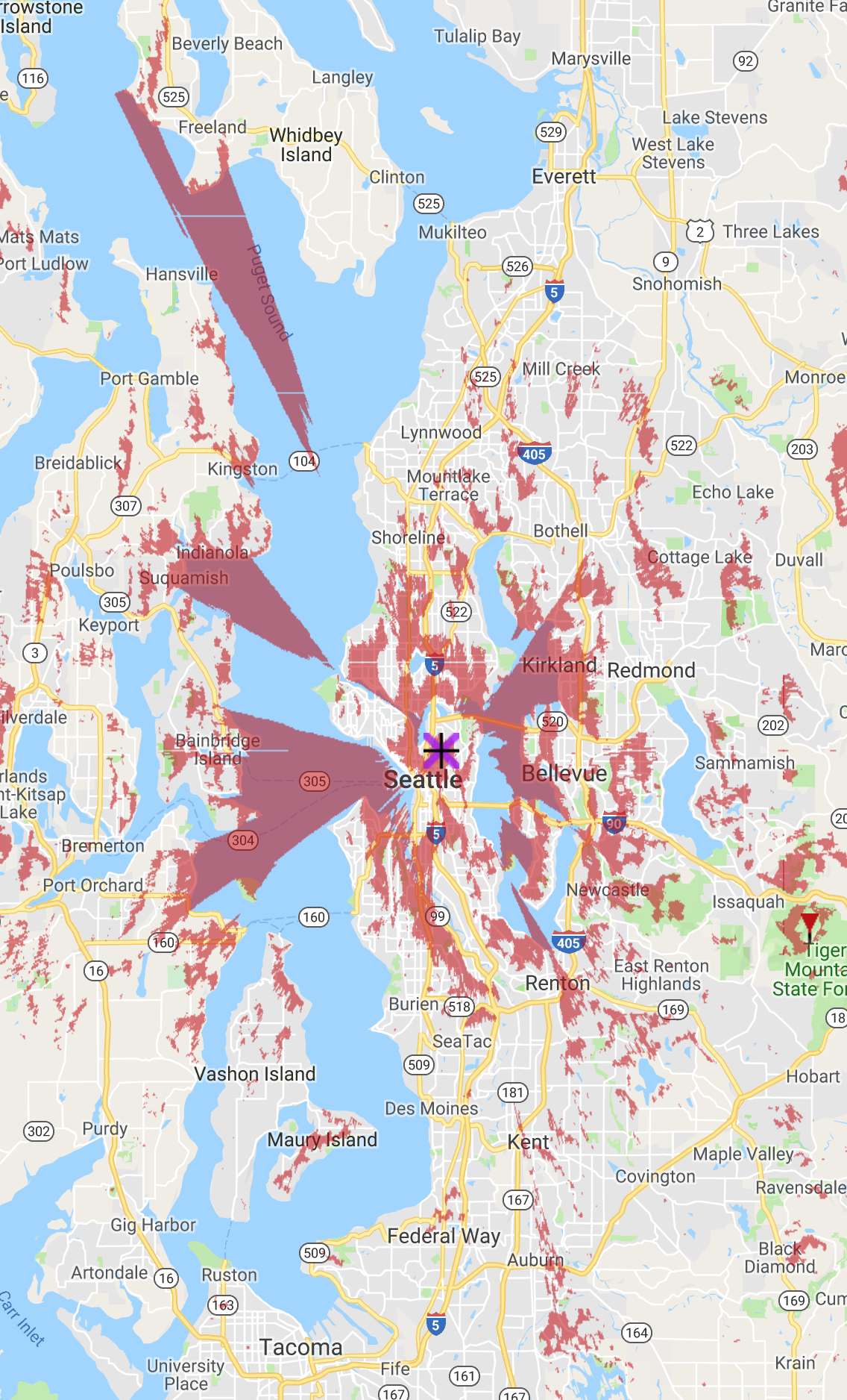
This is the primary transmitter and receiver site. Capitol Park is a 12 story Seattle Housing Authority building on Capitol Hill. The repeater is an MTR-2000. It was formerly controlled by an analog Arcom Controller. The combination of the RTCM and voter module and AllStar linking controller software (all running on a Raspberry Pi 3) now completely replace the Arcom controller and provide more control and more functionality. The interface cable is purpose built to interface the MTR2000 to the RTCM and is provided by Northcomm Technologies Group.
Beacon Tower
Beacon Tower is a 16 story Seattle Housing Authority building on Beacon Hill and is our backup repeater site and the location of one of our satellite receivers. This site uses a Kenwood TKR-750 repeater. Beacon Tower is also a HamWAN cell site with good connectivity to other HamWAN locations and direct connectivity to Capitol Park. We will also locate one of the voter systems here due to its close proximity to one of our transmitters and the good colocation with HamWAN.
Buck Mountain
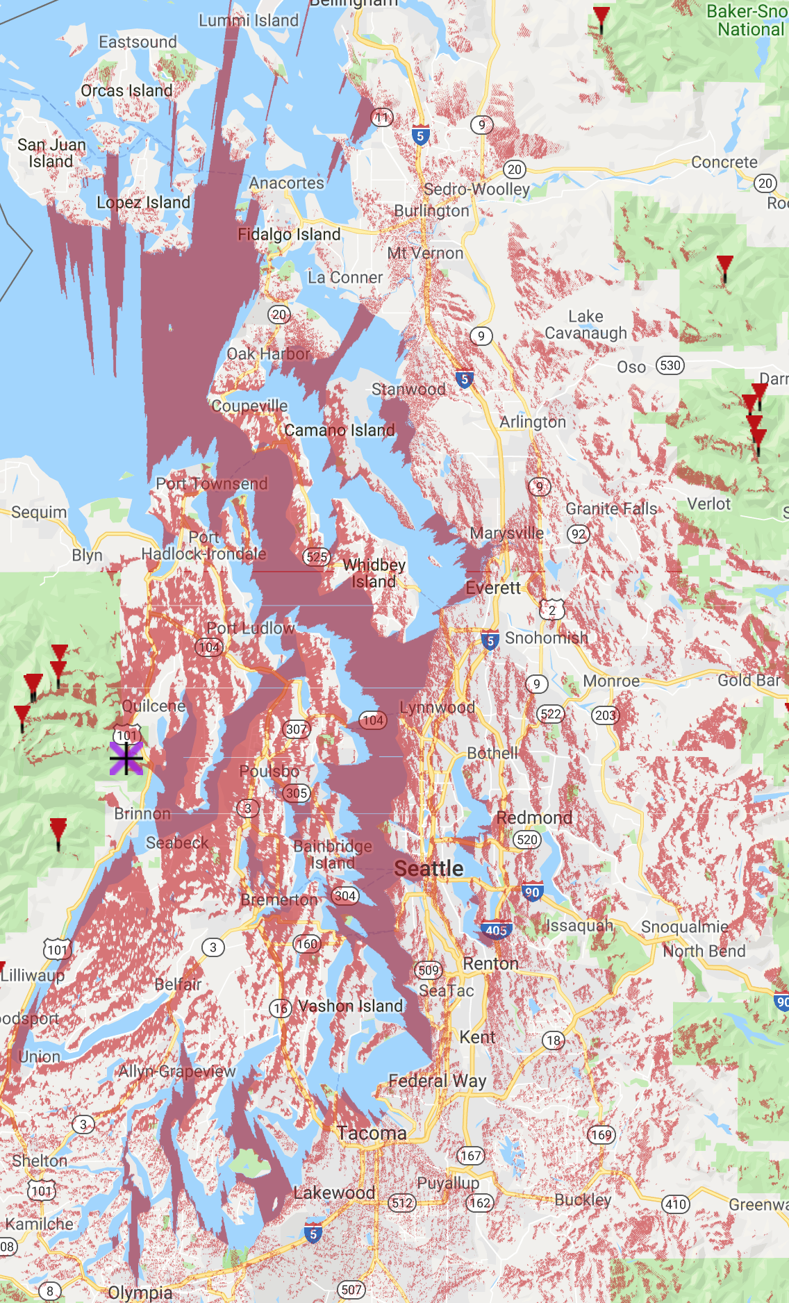
Buck Mountain is on the Olympic Peninsula, above Dabot Bay. Buck Mountain is a new HamWAN site and we connect directly to the HamWAN router there. This site is directly connected to Capitol Park over a 5GHz HamWAN link. (Motorola CDM1250)
Cougar Mountain
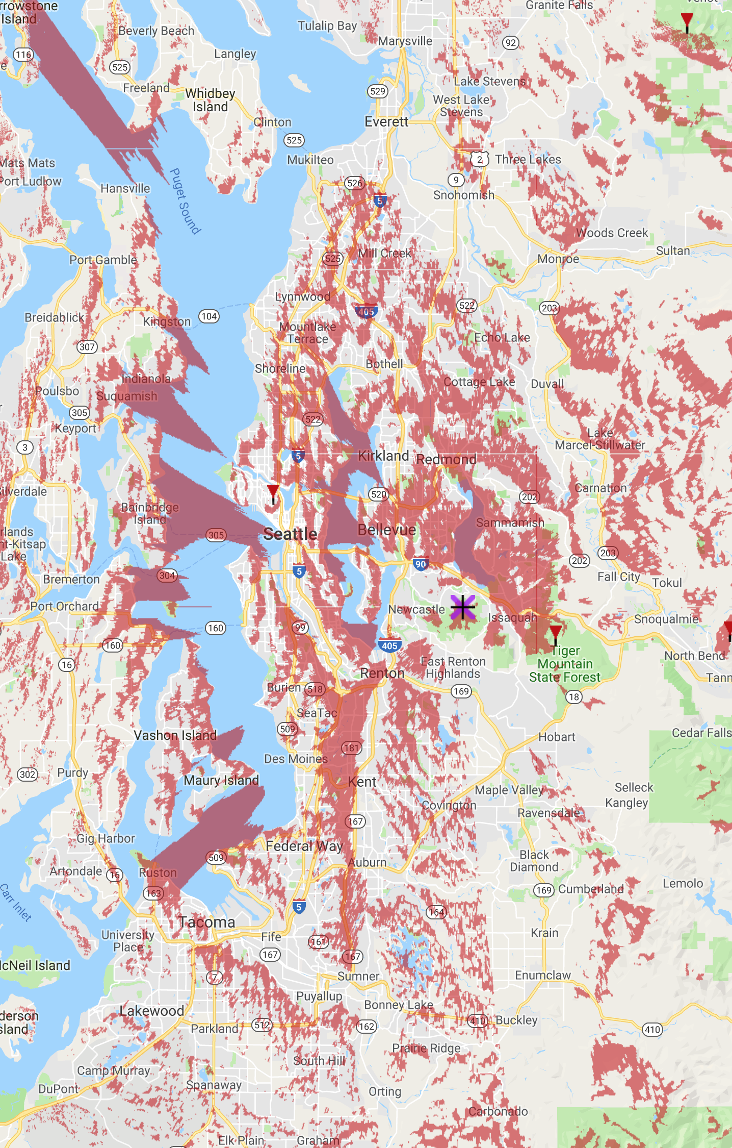
Cougar Mountain is just south of Lake Sammamish, east of Seattle. This site currently uses a commercial internet link back to the voting system. (Motorola CDM750)
Lake Forest Park
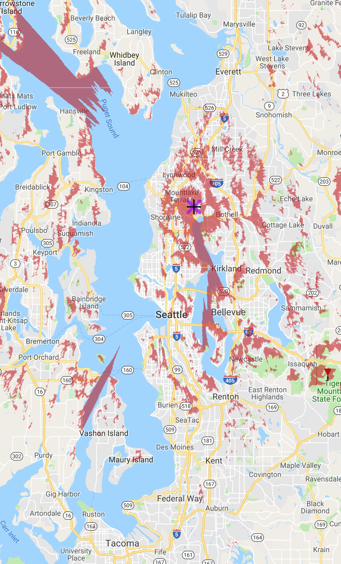
Lake Forest Park is a 48 foot tower at the Seattle Public Utilities reservoir north of Lake Washington and at a ground elevation of 500 feet AMSL. The HamWAN connection at LFP connects to Capitol Park sector 1. (Motorola CDM750)
Magnolia
This site is located on Magnolia Manor Park, at the north end of Magnolia. It provides good coverage in the city, and the Puget Sound shorelines. It uses a HamWAN connection via Haystack Mt. back to the voting system. (Motorola CDM750)
Queen Anne
This site is no longer in use.
General notes on satellite receivers
The basic satellite receiver is based on a Motorola CDM750 or CDM1250 mobile radio with a preselector filter for improved selectivity and isolation from RF interference or de-sense. The RTCM interfaces on the accessory connector on the rear of the radio. The transmitter is disabled on the radio.
Capitol Park
Beacon Tower
![]()
Cougar Mountain
Lake Forest Park
Buck Mountain
Monitoring
You can look at the strength of the signals being received by each of the receivers in real time at the PSRG Supermon page.
 Winter Field Day, January 24-25 (